1.Single Speed Elevators:
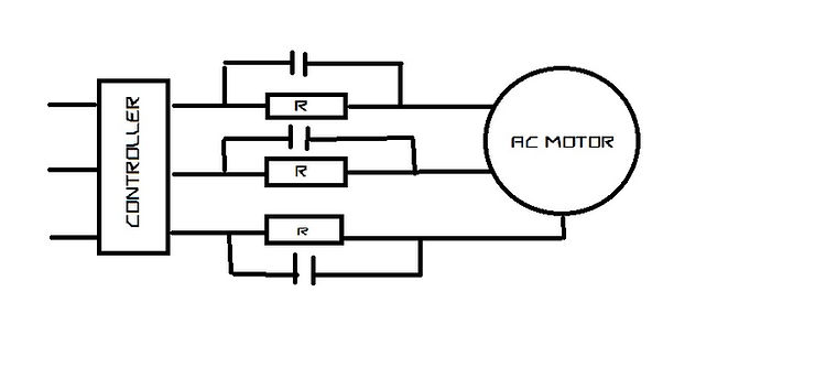
These are the most common type of low capacity, slow speed, low cost passenger elevators intended to service buildings in the two to right floor ranges. These are elevators at 0.63mps where car speeds and passenger comfort are less of an issue. In this type of elevator motor power is switched directly on line and stopped by the removal of electric power and application of brake simultaneously. In certain types, a step of resistance my be introduced between the motor and the lines to reduce the inrush current when the motor is started and the resistances shorted when the motor attains normal speed. With this arrangement, the starting jerk is reduced to a certain extent. These types of elevators are still most popular in low cost, low rise residential buildings.
For lifts up to 0.63mps and 550kg capacity, the Indian standard allows levelling inaccuracy of +/- 75mm(max).
Disadvantages:
- Poor ride Quality – Acceleration, Deceleration. Vibration and stopping Jerk.
- Poor leveling accuracy- In this type of elevator control, it is extremely difficult to consistently bring the car to a stop in the same spot where it is level with the floor. There are several reasons for this inconsistency. Varying load conditions affect the ability of the brake to stop consistently at level. The brake tension springs have been set for a “typical” Loading condition and then set to stop the car level with the floor. A heavier load will cause the car to slide a little further (travel past the floor) when it stops and a lighter load will cause the car to stop a little sooner (stop prior to floor level). The counterweight is always about 40% to 45% heavier than the empty car, thus an empty car will have a different stopping condition then a fully loaded car.
- The speed of the elevator gets affected by the slight variations in the line supply frequency or voltage, thus affecting the leveling accuracy.
- Tripping hazard due to poor leveling accuracy.
- Not suitable for wheel chair applications.
- There is no motion control circuitry for relevelling.
2. Two Speed Elevators:
Further refinements of alternating current motor control include the use of two speed motors with ratios of 4:1 between the low speed and high speed windings. The speed of the elevator could be increased from 0.63mps to 1mps with two speed elevators. The elevator runs with the high speed winding and is switched to the lower speed winding when it is near the floor stop. Final stopping is done with the brake, simultaneously removing the power to the motor. In order to reduce the starting currents and jerk during switching from fast to slow speed windings, resistors were introduced between the line and the respective motor windings which get bypassed once the rated motor speed is achieved. For lifts up to 1mps and drives with two speed motors having a ratio of 1:4 between high speed and low speed are allowed max +/- 25mm leveling accuracy as per IS 14665 (Part 3 / Sec 1):2000 Para 10.
Disadvantages:
Two speed elevators have all the disadvantages of single speed elevators. These types of elevators have become obsolete in India owing to the availability of cost effective better speed control methods.
3. Variable Speed Control:
3.1 Ward – Leonard Speed Control:
The Ward Leonard control system was widely used for elevators until thyristor become available in the 1980s, because it offered smooth speed control and consistent torque. The speed control of DC motor accomplished by means of an adjustable voltage generator is called the Ward Leonard system.

The Ward Leonard configuration consists of a constant flux DC motor and a rotating conversion AC motor DC generator set. As shown in fig above, M1 is the main motor whose speed control is required. The field winding of this motor is permanently connected to DC supply and armature is fed from variable voltage so that the motor can run at an desired sped. To provide this variable voltage, a motor DC generator set is used in which the generator is directly coupled to a constant speed motor. The armatures of the generator and the motor are directly electrically connected. The field of the generator is excited from a variable and reversible DC source thus the generator output voltage can be varied from 0 to maximum in both directions. This system of speed control is commonly used in elevators as this can give speed control in either direction. Since the generator output voltage can be increased from zero, no extra starting equipment is required to start up the main motor smoothly. Ward Leonard system is a classic high quality elevator drive arrangement found in the vast majority of better quality geared and gearless installations built before 1990. The important feature of the Ward Leonard system is its regenerative action.
The fundamental principles of DC variable speed drive, with shunt wound DC motor are relatively easy to understand covered by a few equations as follows:
The Armature Voltage ‘VA’ is equal to the sum of Back EMF of Motor ‘VE’ and the voltage drop due to armature current flowing through the armature resistance.
Hence Armature Voltage VA= VE + IA * RA
The DC motor speed ‘n’ is directly proportional to the motor back EMF ‘VE’ and inversely proportional; to the field flux ‘Φ’ . The flux is proportional to the field current ‘IE’.
- Motor Speed n ∝ VE / Φ, Motor speed can be varied either by varying VE or Φ
- The output torque of the DC motor ‘T’ ∝ IA * Φ
By changing the direction of Armature current or by changing the direction of filed current, the direction of rotation or the direction of the torque can be changed.
- The output power of the motor P= T * n
From the above, following conclusions can be derived:
- The speed of the DC motor can be controlled by adjusting either the armature voltage or the field flux or both. For elevator applications the field flux is kept constant and the motor speed is varied by increasing the armature voltage.
- When the Armature voltage VA has reached the maximum voltage, it is possible to increase the motor speed by reducing the field flux. This is known as field weakening method.
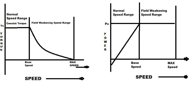
- Since the torque is not dependent on VA, the full load torque output is possible over the normal speed range even at stand still (Zero Speed).
- The output power is zero at zero speed. In the normal speed range at constant torque, the output power increases in proportion to sped.
- In the field weakening range, the motor torque falls in proportion to the speed. Consequently the output power of the DC motor remains constant.
Torque and power characteristics of a DC motor over its speed range is shown below;
Advantages of Ward Leonard system:
- A wide range of speed from stand-still to high speed in either direction.
- Has good speed and torque characteristics and could achieve a speed range of 25:1.
- Extremely good speed regulation.
- Regenerative action.
Disadvantages:
- High initial cost due to motor generator set.
- Occupies more space.
- Low overall Efficiency.
- High maintenance cost primarily due to wear and tear of commutator and brushes.
- Mechanical commutator and brushes impose restrictions on ambient temperature and humidity.
- High thermal losses in the machine room.
- High Noise levels.
Similar to 2 speed elevators, these types of elevators also have become obsolete in India owing to the availability of cost effective better speed control methods.
3.2 ACVV (AC Variable Voltage) Speed Control:
In this method, the voltage applied to the three phase windings of low cost squirrel cage induction motors were controlled with the help of thyristors. The deceleration was achieved by DC injection into the windings. The resultant speed control is smooth and step less, making it suitable for passenger elevators.
Demerits:
- High motor slip caused by the constant frequency of the variable voltage causes large thermal losses with resultant low operating efficiency.
- The chopper which is used to provide the variable voltage control introduces undesirable harmonics into the power system thus causing malfunctions to the other electronic systems connected to the same power system in the building.
- These harmonics cause undesirable radio noise and can cause system component overheating.
- The system’s low power factor increases line losses and necessitates increased feeder sizes.
As a result of the demerits, this speed control system which was applicable to low and midrise passenger service with speeds up to 1.75mps has been replaced by VVVF controls. The ACVV elevator speed control has now become obsolete.
3.3 ACVF / VVVF Speed Control:
Both the voltage and frequency of the motor winding are varied to control the speed of the motor. IGBT (Insulated Gate Bipolar Transistors) are used to accomplish the voltage and frequency changes. Since the speed of the induction motor is proportion to the frequency of the supplied power, the speed of the motor is varied. Both the voltage and frequency are varied to control the torque and current.
The system consists of a rectifier, which changes the incoming AC to DC, and an inverter which creates variable voltage and variable frequency three phase AC from the rectified DC voltage. This output is then applied to a standard squirrel cage induction motor which operates essentially at the speed corresponding to the frequency. By maintaining a constant frequency to voltage ratio input to the traction motor, it is possible to provide continuously variable highly accurate speed control throughout the full speed range of the motor. The VVVF speed control system eliminates most of the disadvantages of the previous ACVV thyristor control system and has the following characteristics:
- Overall system efficiency high at all motor speed.
- Use of Economical commercially available Squirrel cage induction motors.
- System power factor closer to Unity.
- Line harmonics are much less than ACVV controls.
- Extremely good speed control and leveling accuracy.
- Uses solid state, thus very low maintenance.
- Electric energy use and peak loads are reduced thus reducing energy bills.
- Brake applied on reaching near zero speed, thus reducing jerk and brake wear and tear.
- The system is suitable for all rises and speeds.
- Machine rooms are smaller, cooler and quieter.
Thanks for reading this blog, for more topic comments the topic name.
Comments